Structural dynamics and numerical analysis
Numerical precision meets dynamic reality – solutions for complex vibration systems
The experienced working group focuses on the dynamic vibration behavior of systems, particularly in the fields of mechanical and automotive engineering, civil engineering, and aerospace. The goal is to capture vibration behavior through measurements, calibrate numerical models using measurement data if necessary, and formulate measures to resolve vibration issues. We offer comprehensive support for short- and long-term measurements in our laboratories or on-site, for determining dynamic forces and system responses, and for detecting unwanted vibration behavior. Advanced methods, innovative software products, and state-of-the-art measurement technology are used in this process.
Our Expertise in Structural dynamics and numerical analysis

Consulting and Optimization
We conduct detailed dynamic analyses, develop precise simulation models, and provide consulting on customized solutions for structural optimization. We are happy to advise you on your individual questions.
- Problem Identification
- Minimization of vibrations and noise
- Identification of weak points
- Identification of complex vibration mechanisms
- Increase in stability
- Identification of fatigue and remaining service life
- Optimal sensor positioning

Operational Vibration Analysis
The Operational Vibration Analysis (OVA) is used to determine vibration behavior under operating conditions, where natural vibrations overlap with forced vibrations. Typical applications include identifying disruptive vibrations in vehicle and rail components, engines, compressors, as well as pressure vessels and pipelines.
Your Benefits:
- Detailed Insights: The interaction of various (machine) components can be visualized immediately after an operational measurement (operational vibration modes). This allows vibration states occurring during operation to be displayed separated by frequency components or significantly slowed down in the case of transient events.
- Detecting Loads: When strain gauges (SGs) are used for operational measurements, component strains under load can be identified. From this, component stresses can be derived, enabling, for example, lifetime calculations.
- Operational Assessment: Based on the measurement data, requirements for vibration levels (limit curves) can be checked to ensure safe operation.
- Flexibility: We use a wide range of sensors and multi-channel measurement systems, allowing us to offer a setup tailored to the measurement task.
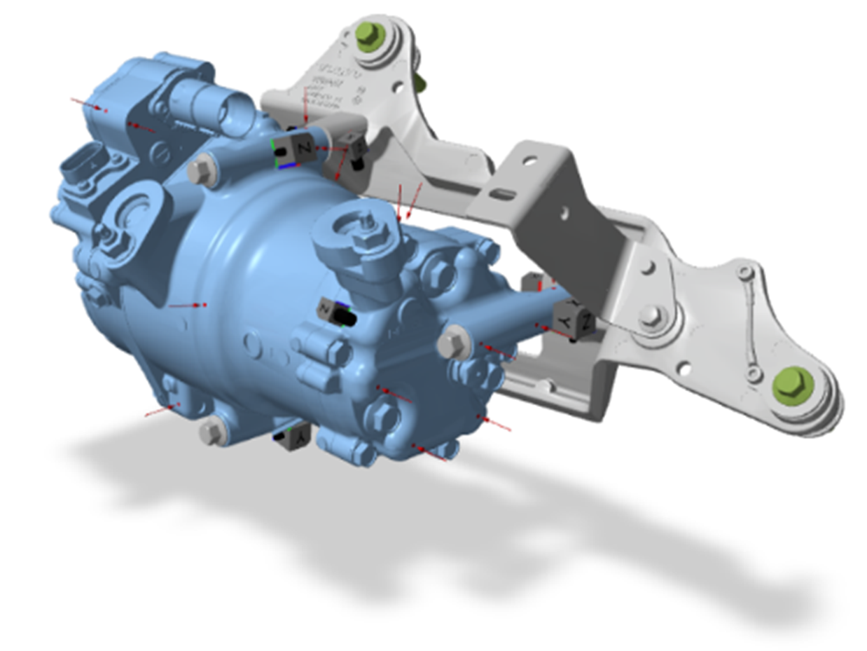
Blocked Force Identification
Characterizing structure-borne noise sources is essential for modeling complete systems and predicting operational behavior. However, the forces and resulting vibrations introduced by a source depend on the specific mounting structure, meaning that forces or accelerations measured on a test rig cannot be directly transferred to a target structure. Therefore, the approach of identifying blocked forces is gaining popularity. This method allows for direct comparison of different component variants and the definition of limit values for suppliers.
To determine blocked forces, we use highly specialized software functions from VIBES.technology.
Variants:
- Direct: Direct measurement of blocked forces is performed using force sensors placed between a vibration source and a test rig. Due to strict stiffness requirements of the test rig, reliable measurement is challenging. Müller-BBM therefore uses an approach that compensates for the test rig’s dynamics.
- Indirect: Indirect measurement of blocked forces is carried out using an impact hammer (with force sensor) and acceleration sensors. The vibration source can be elastically mounted (free-free), installed in a test rig, or located in its actual installation environment (in-situ method).
Your Benefits:
- Transferability: Blocked forces determined on a unit can be transferred to any receiver structure in modeling. This enables commonly used components to be evaluated for new designs in advance.
- Reliability: Identifying structure-borne noise sources through measurement sounds simpler than it is in practice. Test rigs are often used to determine force input, but their data may not yield reliable results. The methods we use reflect the current state of the art and research.
- Communication: Blocked forces can facilitate cross-company product development. Suppliers often have limited data on the structural dynamic properties of a product, meaning that while a component’s performance can be assessed on a test rig, it may differ significantly when integrated into the final product. This method enables product developers to define specifications and limit values that suppliers can verify on the test rig.
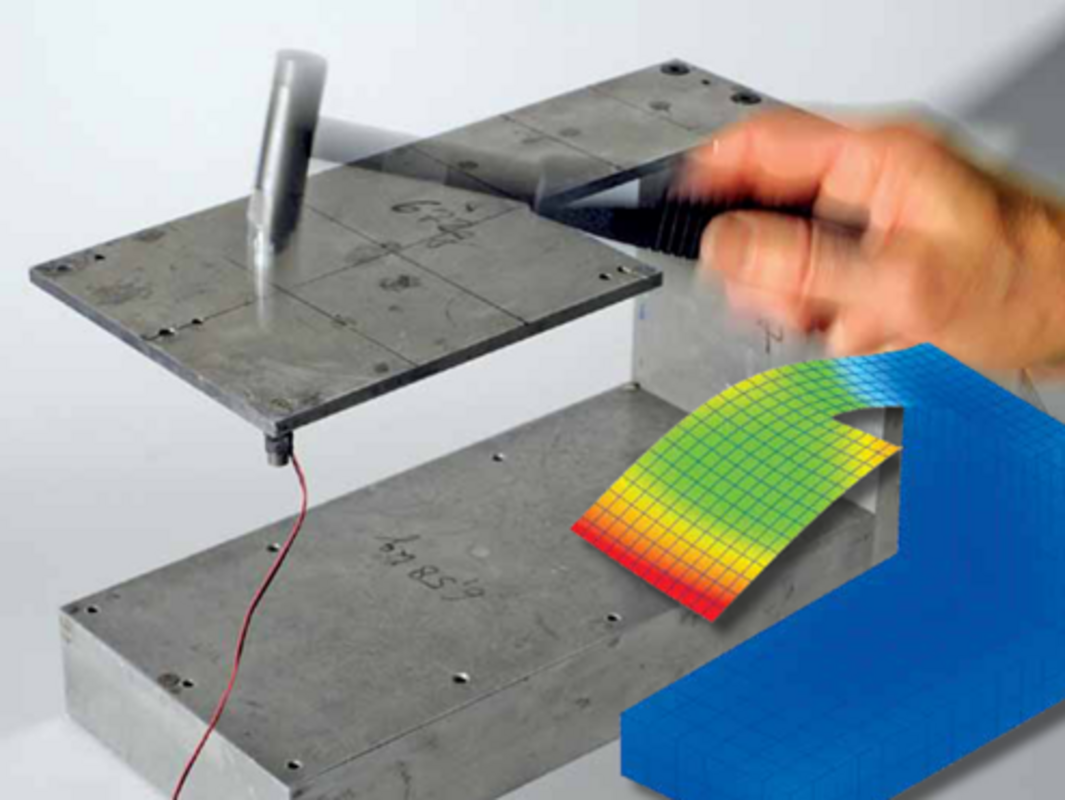
Experimental Measurement
Our multi-channel measurements for recording accelerations, vibration velocities, displacements, and strains—using conventional sensors or contactless methods (e.g., laser- or camera-based techniques)—enable detailed analysis of dynamic properties.
We offer all measurement-related services from a single source:
- Hardware: We use equipment from our sister company, Müller-BBM VibroAkustik Systeme GmbH, for high-precision data acquisition and maintain a wide range of sensors, shakers, and impulse exciters on-site.
- Software: Data preprocessing is primarily carried out using our in-house software (e.g., PAK).
- Vibration Laboratory: In our labs, we can prepare and conduct customer-specific analyses.
- On-Site: We specialize in enabling measurements even under the most challenging conditions. We are happy to perform measurements directly at your location.

Mount Characterization – Dynamic Stiffness
For the modeling and optimal design of elastically mounted components, knowledge of the dynamic stiffness of the mounting elements is essential. However, developers often have only limited data available (frequency range < 30 Hz, restricted to axial and transverse stiffness). In addition to our test bench for dynamic stiffness, we also apply the indirect method based on impact hammer measurements, which is particularly recommended for smaller elements under moderate preload conditions.
Your Benefits:
- 6 Degrees of Freedom: Dynamic stiffness can be determined in a single measurement for all three translational and rotational degrees of freedom.
- Extended Frequency Range: The dynamic stiffness curve can be determined up to the kHz range (~3 kHz), making it suitable for acoustic modeling.
- Proven and Innovative: The development of this method has been significantly advanced by our partner VIBES.technology and implemented in their software products. This ensures high-quality and reproducible stiffness curve determination.
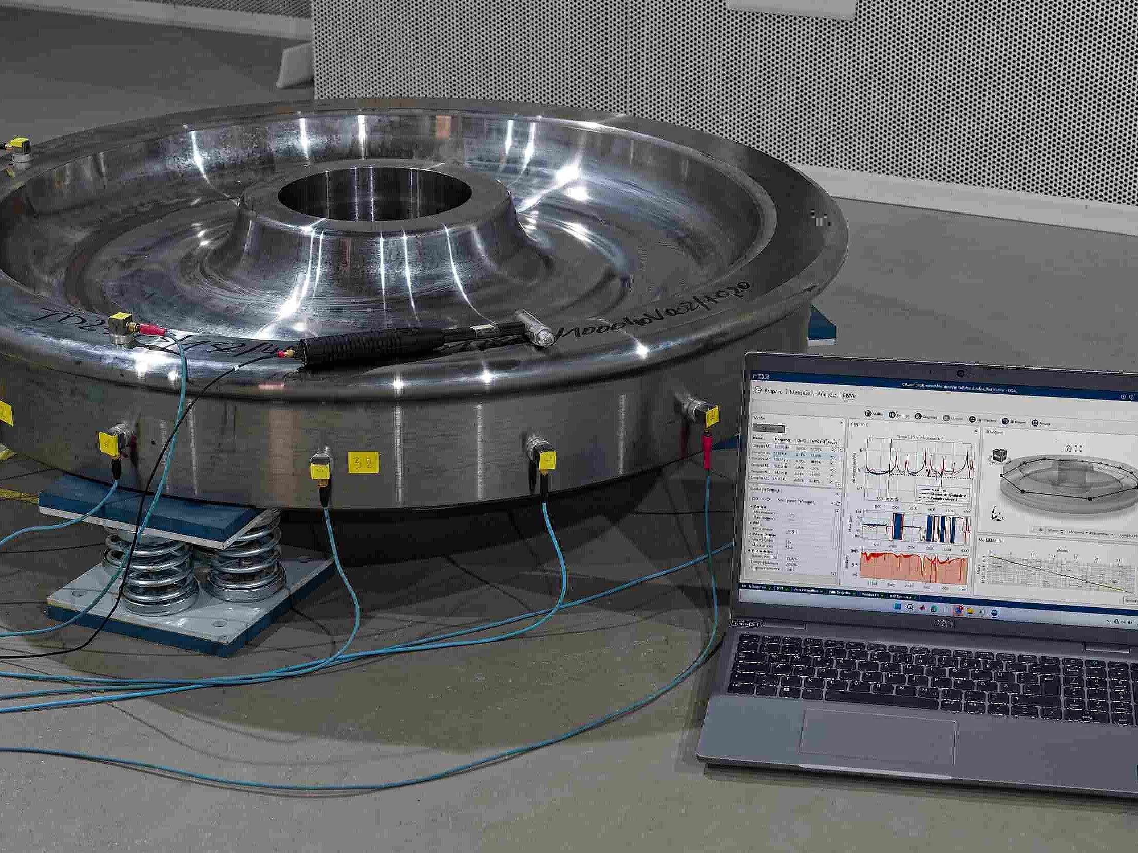
Modal Analysis
Modal analysis is a suitable method for identifying load-independent vibration behavior and thus controlling resonance effects. Typically, natural frequencies, mode shapes, and damping ratios are determined and then specifically modified through structural measures. To determine modal parameters, we use advanced techniques such as the p-LSCF method and the SSI method.
Variants:
- EMA (Experimental Modal Analysis): In experimental modal analysis, both system excitation and vibration response must be measured. Excitation is typically performed using an impact hammer or shaker within the investigated frequency range.
- OMA (Operational Modal Analysis): Operational modal analysis is suitable for applications with unknown system excitation. It is particularly useful for large structures that cannot be sufficiently excited or very small structures where controlled force application is not feasible.
- Numerical: In numerical modal analysis, the structure is modeled using the finite element method (FEM), and natural frequencies, etc., are calculated numerically. Experimentally validated models (via EMA) are often used for comparison and to predict design modifications.
Your Benefits:
- Detailed Understanding: The vibration behavior of (machine) components or systems can be visualized (mode shapes) and evaluated. The results can be used to create numerical models.
- Reliable: The SSI method allows confidence levels to be derived for the identified parameters, increasing trust in the results.
- (Not) Hard to Reach: Thanks to the optional use of the virtual point transformation method, EMA can also be performed on objects with conventionally hard-to-reach excitation positions and directions—an area where EMA quality is often limited.
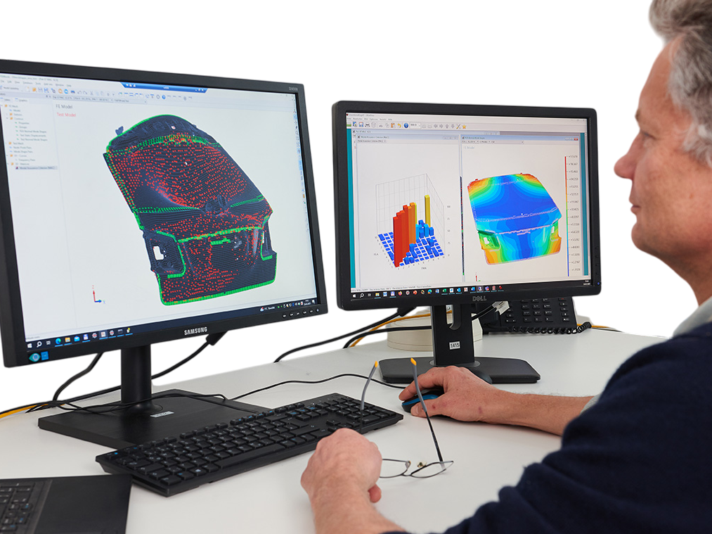
Model Calibration (Model Updating)
Every model is based on assumptions and simplifications, which can lead to the modeled structure behaving differently than its real-world counterpart. That’s why we use a variety of methods to calibrate numerical models using experimental measurement data.
The following methods are used as standard:
- Static Measurements: By comparing static measurements such as strains and displacements, static structural models can be calibrated.
- Dynamic Measurements: We also offer calibration methods based on dynamic measurements, such as natural frequencies, mode shapes, and damping ratios.
- Stochastic Models: For model parameters with high variability, stochastic models can be calibrated, where parameters are described using distributions.
Your Benefits:
- Increased Efficiency: Manually adjusting parameters can be time-consuming. Our team uses FEMtools, a state-of-the-art software for model updating, enabling efficient processing.
- Greater Confidence: A simulation chain composed of components that haven’t been validated with measurements introduces uncertainty regarding safe and low-vibration operation of the overall system. A calibrated model builds trust in the analysis results.
- Improved Goal Achievement: Numerical design optimization and operational analyses for evaluating loads and vibrations are more reliable when based on a sufficiently calibrated model.
We primarily use FEMtools for model calibration.
Numerical analysis and modeling
Numerical analysis focuses on the modeling and simulation of the dynamic behavior of structures as well as acoustic properties. Simplified models or numerical computer models are used to predict the response of systems and machines to vibrations, impacts, and other dynamic influences, or to investigate resonance behavior. We provide consulting for the analysis of linear and nonlinear systems and routinely apply the following models:
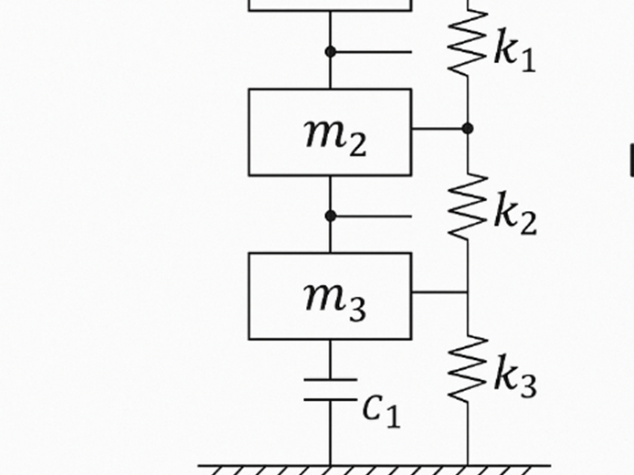
- Multi-degree-of-freedom oscillators: Even complex structural dynamic systems can often be approximated using simplified engineering models. These models are suitable for describing the fundamental properties of coupled systems and for preliminary design.
- Acoustic simulation: Using coupled models (structure and fluid), vibration-induced sound radiation from components can be calculated and acoustic measures evaluated. In addition to commercial simulation software, we also use a range of internally developed methods to compute acoustic parameters.
- Finite Element Models (FEM): The finite element method is a widely used tool for replicating structural dynamic and acoustic systems in computer models, predicting system behavior, and optimizing vibration and radiation characteristics.
- Boundary Element Method (BEM): This method is particularly suitable for modeling and analyzing phenomena related to acoustic radiation. Due to its relatively low computational cost, acoustic effects of large structures or at significant distances from the source can be efficiently represented and studied.
- Model Reduction: To efficiently compute complex models, we use established model reduction techniques and surrogate models. This saves us time—and saves you money.

Vibration-Based Design
As part of vibration-based design processes, we configure a system or component to exhibit the desired vibration and damping characteristics. The goal is to control resonance effects and limit vibration transmission to adjacent components. This enhances user comfort, extends component lifespan, and improves the manufacturing precision of machines. From planning to measurement-based validation of the measures, we offer all services from a single source.
Service Highlights:
- Vibration Absorbers: In English, a distinction is made between neutralizers and absorbers. Depending on the application and positioning, a (damped) absorber either compensates for excitation forces or acts as an absorber/damper for natural frequencies. For optimal performance, the parameters—mass, stiffness, and damping—should be precisely tailored to the application.
- Vibration Isolation / Mount Design: Specialized machine feet, elastomer mounts, or foundations isolate vibrations from machines and components, thereby reducing transmission to adjacent parts.
- Structural Optimization: Design modifications such as added masses or stiffening elements detune the dynamic system and can prevent resonance during operation.
- Operational Optimization: Adjusting the rotational speed of rotating components can help avoid excitation in critical frequency ranges, thereby reducing vibrations.
Your Benefits:
- Experience: We have many years of experience with a wide range of machines and components. Often, an external perspective helps to better understand vibration-related issues or develop new ideas.
- Outsourcing of Specialized Services: If in-house vibration design is not feasible due to lack of software tools or capacity constraints, we are happy to provide tailored support.

Software Consulting
We are independent consultants and an official distribution partner for FEMtools, as well as a partner of VIBES.technology. The following software products are part of our standard toolkit:
- ME'scope – A professional software focused on experimental analysis and the investigation of structural vibration behavior.
- FEMtools – A premium software package for static and dynamic simulations, model updating, topology optimization, and structural health monitoring. It is widely used in our workflows for efficient and high-quality model calibration
- Software from VIBES.technology – VIBES.technology offers innovative measurement methods and software products such as DIRAC, SOURCE, and COUPLE for blocked force measurements, experimental modal analysis, and substructuring. They also introduced the virtual point transformation method. Their tools are integrated into workflows involving MATLAB and CAE-based platforms like ANSYS, COMSOL, and NASTRAN
- ANSYS – A comprehensive simulation software for modeling, simulating, and optimizing multiphysics processes, including static and dynamic problems, fluid dynamics, optics, acoustics, electrical and magnetic phenomena, and digital twins.
- COMSOL – Another powerful tool for multiphysics modeling and simulation, covering similar domains as ANSYS and supporting digital twin development.
Programming – We also offer custom programming services for project-specific challenges and maintain proprietary libraries in Python, MATLAB, and Octave to support all described services

Structural Health Monitoring (SHM)
Structural Health Monitoring (SHM) refers to the continuous and systematic monitoring of load-bearing structures in civil engineering, mechanical engineering, and aerospace. In civil engineering, it is also known as building monitoring and is used for bridge monitoring, among other things. Structures are permanently equipped with sensors that automatically preprocess measurement data and, if needed, transmit it to online servers. As described by the German Federal Ministry for Digital and Transport (BMDV), the combination of SHM and on-site inspections forms the foundation for digital twins, which in turn serve as a decision-making basis for structural engineers and maintenance personnel.
- Software Development: We develop software for the design of SHM systems. Unlike other providers, our solutions empower clients to design SHM systems for any type of structure and sensor—without any programming knowledge.
- Data and Communication Management: Our software handles all tasks from the measurement system to your desk: preprocessing data at the structure, long-term storage, and (optionally) online transmission to a server with custom dashboards.
- Cost-Benefit Analysis: The value of SHM systems depends not only on the sensors used and their cost but also on the algorithms applied. Our software includes innovative methods to assess the added value of monitoring.
- Consulting and Testing: We are happy to support your SHM project by designing SHM systems and conducting short- and long-term tests. Additionally, we review monitoring concepts as independent experts under the four-eyes principle.
Dynamic substructuring
Complex systems are rarely fully represented by a single model. If a substructure is modified, the entire model would need to be reassessed. Therefore, the substructuring method follows the approach of assembling a complete model from various submodels. Individual components of a system are characterized either experimentally or numerically and then integrated into the overall model. This enables rapid evaluation of component effects on overall system behavior. In addition to classical numerical methods, predominantly experimental approaches to full-structure analysis also exist.
We apply specialized measurement techniques from VIBES.technology as well as numerical methods using FEMtools and ANSYS.
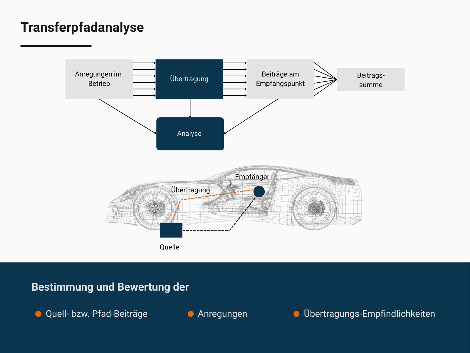
Transfer Path Analysis (TPA)
Transfer Path Analysis (TPA) is a method used to investigate the transmission paths of airborne and structure-borne noise from their sources to the receiving location. It is suitable for identifying and evaluating propagation paths.
Variants:
- Classical TPA: The analysis is performed on the final system design based on measured or derived (interface) forces. However, the identified forces and path contributions are only valid for the tested configuration and cannot be transferred to modified receiver structures.
- Component TPA: Based on the Blocked Forces method, the source is identified as a receiver-independent quantity. This means that when modifications are made, only the transfer paths from the interface to the receiver need to be re-evaluated—not the source itself.
- Operational TPA (OTPA): Particularly useful for existing designs where unexpected vibrations occur, OTPA can offer a cost-effective alternative to classical TPA. The method does not require force identification and focuses on identifying dominant transmission paths.
Your Benefits:
- Improved Understanding: These methods allow for a better understanding of complex systems in terms of their transmission mechanisms, enabling targeted design modifications.
- Control of Energy Flow: Improvements to a single component may be ineffective if equivalent paths are not also optimized. TPA helps reduce unnecessary redesign cycles.
- Quieter Products: Optimized transmission paths lead to reduced vibrations and a quieter environment at the receiver.
In the field of TPA, we work closely with our colleagues in rail and vehicle acoustics.
Do you have any questions?
Feel free to reach out to me!
-
 Dr. Oliver Heuss
+49 (89) 85602-3285 +49 (89) 85602-111 oliver.heuss@mbbm-ind.com Planegg/Munich